LUNCH & LEARN - Book an informative, virtual or in-person discussion for you and your team. Learn more here

F3.00/ F3.01 Paddle Wheel Flow Sensors

CPVCPVDF316L SS
Series: F3.00/F3.01 Paddle Wheel
Rotor: ECTFE (Halar)
Shaft and Bearings: Ceramic, 316L Stainless Steel (only for metal sensors)
Seals: EPDM, Viton
Pipe Sizes: 1/2″ – 24″
Velocity Range: 0.15 to 8m/s (0.5 to 25 ft./sec.)
NSF

Contact Us

Name
Address(Required)
I Require *(Required)
My Need Is *(Required)
What's the best way to reach you? (Select all that apply)
Best time(s) to reach you:
Get connected! Stay up-to-date on new developments and industry innovations.(Required)
Privacy Policy and Data Usage Policy Acknowledgment *(Required)
* required field

Description

Type F3.00/F3.01 Paddle Wheel Flow Sensors

The Type F3.00/F3.01 Paddle Wheel Flow Sensors are the core items in the Digiflow FlowX3 line. A square wave output signal is generated with frequency proportional to rate of rotor rotation and flow velocity. This pulse output is normally fed to a FlowX3 flow monitor/transmitter, blind transmitter, batch controller or adjustable flow switch. It can also be fed to other brand instruments or PLC’s.

Three types of sensors are available, Hall Effect which requires a 5 to 24 VDC power supply, Coil Effect which operates with less power, 3 to 5 VDC and Push-pull sensors for safe connection to any NPN or PNP inputs. Coil is required with the battery powered flow monitor. Hall Effect signals may be transmitted up to 300 meters (984 ft.) without the need for conditioning whereas Coil Effect signals may be transmitted up to 16 m (52.5 ft.) without conditioning.

They are available in two sensor sizes L0 and L1 which cover pipe sizes from ½” to 24″, flow velocity range is 0.15 to 8 m/s, with maximum pressure rating 150 psi.

Connectable Instruments:

F3.01.H Hall Effect – Panel/Wall Mount – M9.00, M9.02, M9.10, M9.50
F3.00.H Hall Effect – Panel/Wall Mount – M9.00, M9.02, M9.10, M9.50
F3.01.C Coil Effect – Direct, Panel/Wall Mount – M9.20
F3.00.C Coil Effect – Direct, Panel/Wall Mount – M9.20
F3.00.P Push-Pull – Connect with NPN or PNP Inputs (PLC)

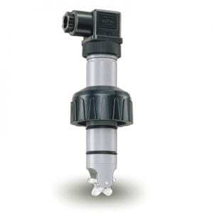
✓ Ceramic Shaft and Bearings
✓ Self Cleaning Design
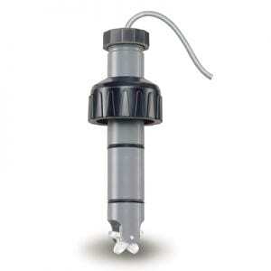
✓ Submersible Sensors Available

Technical

Compatibility

Hall Effect Paddle Wheel Flow Sensors require a supply voltage between 5 and 24 VDC and is normally fed to a F9.00, F9.02, F9.03 or F9.50 flow monitor which will supply power to the sensor. Hall Effect signals may be transmitted up to 300 meters (984 ft.) without the need for conditioning.
F3.00.H/F3.01.H Compatibility Chart

Coil Effect Paddle Wheel Flow Sensors require a supply voltage between 3 and 5 VDC and are required with the battery powered flow monitor. The signal is normally fed to the F9.20 battery powered (3.6 V) flow monitor, which will supply power to the sensor. Coil Effect signals may be transmitted up to 16 m (52.5 ft.) without conditioning.
F3.00.C/F3.01.C Compatibility Chart

Push-pull Paddle Wheel Flow Sensors require a supply voltage between 12 and 24 VDC. The signal is fed to any PLC or flow monitor with NPN or PNP input. Hall Effect signals may be transmitted up to 300 meters (984 ft.) without the need for conditioning.
F3.00.P Compatibility Chart

Instruments

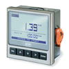
Connectable FlowX3 Instruments
F3.01.H Hall Effect – Panel/Wall Mount – M9.00, M9.02, M9.10, M9.50
F3.00.H Hall Effect – Panel/Wall Mount – M9.00, M9.02, M9.10, M9.50
F3.01.C Coil Effect – Direct, Panel/Wall Mount – M9.20
F3.00.C Coil Effect – Direct, Panel/Wall Mount – M9.20
F3.00.P Push-Pull – Connect with NPN or PNP Inputs (PLC)
Instrument M9.00.TM9.00 M9.02.TM9.02 M9.10.TM9.10 M9.20.TM9.20 M9.50.TM9.50
Compatibility Chart
Power Supply 12-24 VDC 12-24 VDC 12-24 VDC 3.6V Lithium
Thionychloride
Size B Batteries
12-24 VDC
Digital Outputs 1 x SSR 2 x SSR 2 x OC – 2 x SSR
Analog Outputs 1 X 4-20 mA 4-20 mA 2 X 4-20 mA – 4-20 mA
Wiring 2-wire 3/4-wire 3/4-wire 3/4-wire
Mechanical – 1 X SPDT 2 X SPDT – 2 X SPDT

Fittings

Installation
Fittings
Size Materials Pressure
Temperature
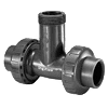
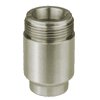
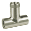
Tees
Socket
Threaded
Flanged
1/2″ to 1-1/2″ Body:
PVC, PP, PVDF Seals:
EPDM, Viton
150 psi @ 20C (70F)
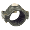
Bolt-On Saddles 1-1/2″ to 12″ Body:
PVC Insert:
CPVC, PVDF Seals:
EPDM, Viton, Nitrile
150 psi @ 20C (70F)
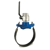
Metal Strap-On
Saddles
3″ to 18″ Body:
Cast Iron/SS Insert:
PVC Seals:
Nitrile
150 psi @ 20C (70F)
Weld-On Adaptors 1-1/2″ to 24″ 316 SS
Carbon Steel
PE
Other materials are available
365 psi with metal F3.00 sensor
316 SS
FNPT Tees
3/4″ to 1-1/4″ 316 SS 365 psi with metal sensor
Plugs for Installation Fittings Body:
PVC, CPVC, PP, PVDF Seals:
EPDM, Viton
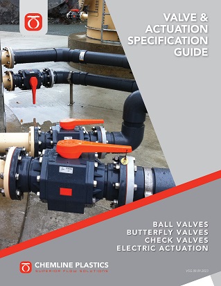
Valve Specification Guide

Valve Specification Guide

Engineering specifications are crucial as they provide precision, clarity, quality assurance and compliance in your projects. Download to save you time and assure accuracy in your specifications.

Download here >
Valve Specification Guide

Chemical Resistance Guide

Corrosion resistance is an important factor in selecting the right material of construction for valves, pipe, tubing, fittings and more. Designed to easily navigate, this guide can be downloaded for easy reference.

Download here >
Materials of Construction Cover Photo

Materials of Construction

Understanding materials of construction is essential to the accurate selection of valves, pipe, tubing, fittings and more. Designed to easily navigate, this guide can be downloaded for easy reference.

Download here >

Responsive Service

Responsive Service

You call. We answer.
Because your call matters.

Our product specialists are available to take your call.
We offer expert technical support and application advice
and make it our business to understand your
requirements and challenges.

Let us help you find the right solution for your application.

Please login to view this document

Don't have an account? Click to Sign Up

Forgot your password?